The usbpicprog hardware is equipped with 2 5-pin headers. 1 is being used to program the bootloader into the usbpicprog hardware’s main controller; this has to happen only once. When the bootloader has been loaded, this connector (P2) will be used to put jumpers to switch from bootloader mode to usbpicprog mode.
The other connector (P1) is the most important connector on the usbpicprog hardware, it has to be connected to the target processor (the one that is going to be programmed).
The connection from Usbpicprog to the target board can be done in two ways; The PIC can be connected directly to the programmer, using a so-called ZIF socket. (In the download section of usbpicprog.org, you fill find a PCB for the ZIF socket).
The most common way to connect the programmer to the target, is through In Circuit Serial Programming (ICSP). This way, a 5-pin header has to be connected to the corresponding pins on the target board, having the following connections:
| Pin on Usbpicprog | Pin on target board | Description |
| VPP | MCLR | The programming voltage, 12V = programming, 5V = run, 0V = reset |
| VDD | VDD, +5V | 5V power supply, can be left open if the target is self-powered. |
| PGD | PGD, mostly RB7 | Programming Data pin |
| PGC | PGC, mostly RB6 | Programming Clock pin |
| GND | VSS or GND | Ground pin, 0V |
Connection of low voltage (18FxxJxx / 18FxxKxx) devices
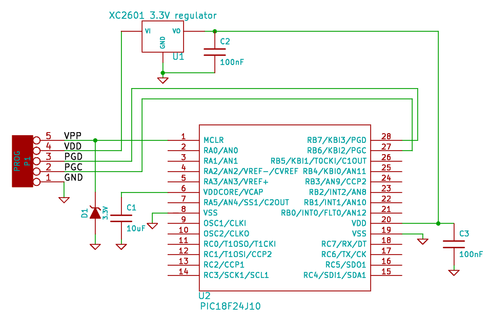
Low voltage devices accept input voltages of 5V on their digital pins, however the power signal needs to be regulated to 3.3V. Also the VDDCore pin needs a capacitor.
Connect these devices as in the schematic below:
